Category Archives: Synths

The SID GUTS Review – Getting retro on my ass

ALM003-clipped-680h-400w

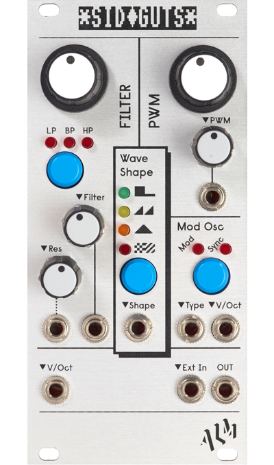
The SID GUTS is a fun little module from ALM that brings a SID chip into Eurorack. If your knowledge of ancient integrated circuits is less than stellar I’ll have you know that SID (Sound Interface Device) is a classic sound generator chip that was used in the Commodore 64 home computer.

The SID GUTS module provides CV-control of an actual SID chip. While it doesn’t utilise all the capabilities of the SID chip;
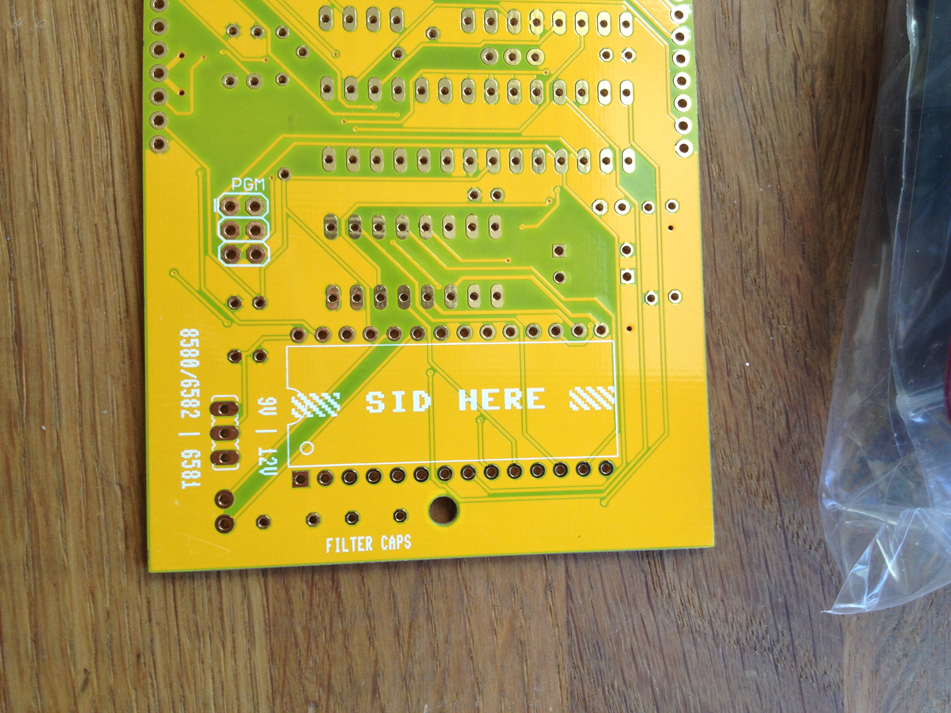
for example the SID has three voices and the SID GUTS only uses one; the SID GUTS is a convenient way of bringing some lo-fi chip-tune sounds into your modular. The module comes without a SID chip, it has a socket in which you mount a SID that you presumably already own. Real SID chips can be hard to find, and draw a lot of power, so an alternative option is using the SwinSID which is a modern SID clone. The SwinSID can be ordered with the SID GUTS and it consumes a lot less power than a real SID which is why I picked a SwinSID for my SID GUTS. The only downside of the SwinSID that I can see is that it doesn’t allow the filter to process external signals. This is no big deal for me because I have a bunch of other filters in my rack already and the SID filter isn’t that impressive to begin with.

So what are the capabilities of the SID GUTS?

Oscillator

As mentioned the SID GUTS provides a single SID voice. The oscillator is a wave-table oscillator with pulse, sawtooth, triangle and noise waveforms. The waveform can be selected manually or it can be cycled from a CV input which can create some pretty glitchy noises. The pitch is controlled by a standard V/Octave CV input. Without modulation or arpeggiation the only waveform that clearly says “C64” is the noise — it is wonderfully steppy and immediately brings to mind a million explosion sound effects from old C64 games.

Noise :

Sawtooth:

Triangle:

Pulse:

Wave-type modulation through CV:

Filter

The filter is an analogue resonant multi-mode filter which is switchable between a 12dB/octave low-pass, a 12db/octave high-pass and a 6db/octave band-pass mode. The high-pass and low-pass modes can also be combined into a band-reject (or notch) mode. The resonance and the cutoff frequency can both be voltage-controlled. As previously mentioned the filter can be used on external signals but only if you have a real SID chip in the module. The filter resonance is quite subtle and, I’m told, varies a lot between different models of SID chip. With the SwinSID the resonance is audible when cranked up to max but I would not go so far as to say that it is clearly audible. At least to not my amateur ears. If I A/B a filter sweep with the resonance at 0 and then at maximum, I could hopefully tell which is which. On the other hand, if I was presented with a single filter sweep and had to tell if the resonance was on or off I’m not sure that I could deliver an accurate verdict.

Low-pass filter sweep with resonance:

PWM

The width of the pulse wave can be changed with the PWM knob or modulated through a CV input. This sounds gorgeous and is, for me, the best bit of the SID GUTS.

Pulse Width Modulation:

Modulation Oscillator

The SID GUTS uses one of the remaining two oscillators in the SID as a modulation source. The modulation oscillator can be used for oscillator sync — the main oscillator waveform is reset at the frequency of the modulation oscillator — or for ring modulation; where both oscillators are set to use the triangle waveform and the result is the sum and difference of the carrier and modulator waveforms.

The SID triangle wave being ring-modulated by another triangle wave.

Oscillator sync:

Modulation type cycled through CV:


In use

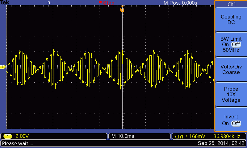
Modulating the oscillator frequency or the pulse width with a CV signal works fine for slow modulation rates. Since the SID only updates its inputs at 50Hz, modulation rates close to or above this rate doesn’t work as expected and you can forget about FM or audio-rate PWM.

I use the Expert Sleepers ES-3 module as my computer-modular interface and it requires a calibration step every time it is started. The calibration consists of the ES-3 sending a range of control voltages to the V/Octave input of the oscillator being calibrated and then detecting the actual output frequencies that are generated by those voltages. This process does not work well with the SID GUTS. In fact, I could not get it to work at all. I suspect that the waveforms generated by the SID are too noisy for the ES-3 calibration plugin to be able to extract a solid frequency from them.

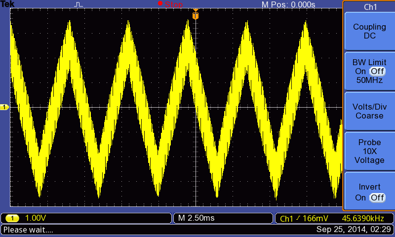
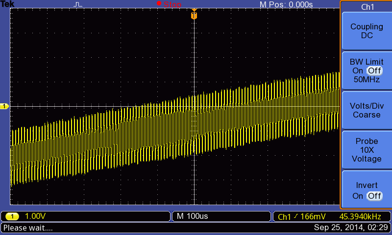
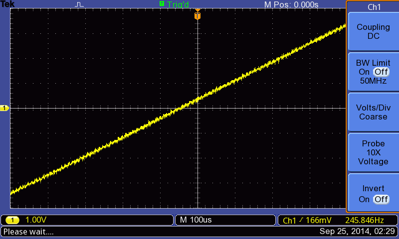
Looking at the waveforms with an oscilloscope it is apparent that there is a constant signal with an amplitude of 2.5V and a frequency of around 1.25kHz superimposed on the wave. This tripped up the auto set function on my oscilloscope and I would guess that this is what confuses the ES-3 calibration as well.

This is the triangle wave from the SID.
If you look closer you see the overlaid signal.
This is the same closeup of the triangle wave from a TipTop Audio Z3000 oscillator. Clinical to some, clean to some.

The SID GUTS excels at chip-tune-like bleeps, bloops and chirps. Playing rapid arpeggios to simulate chords with a single voice still gets you that Rob Hubbard feel which I presume is the reason you would want a SID-chip in your modular.

Arpeggio:

I tried to play the theremin part of the Doctor Who Theme but was bested. A 2-octave portamento glide sounded truly horrible, and not in a good way.

Building it

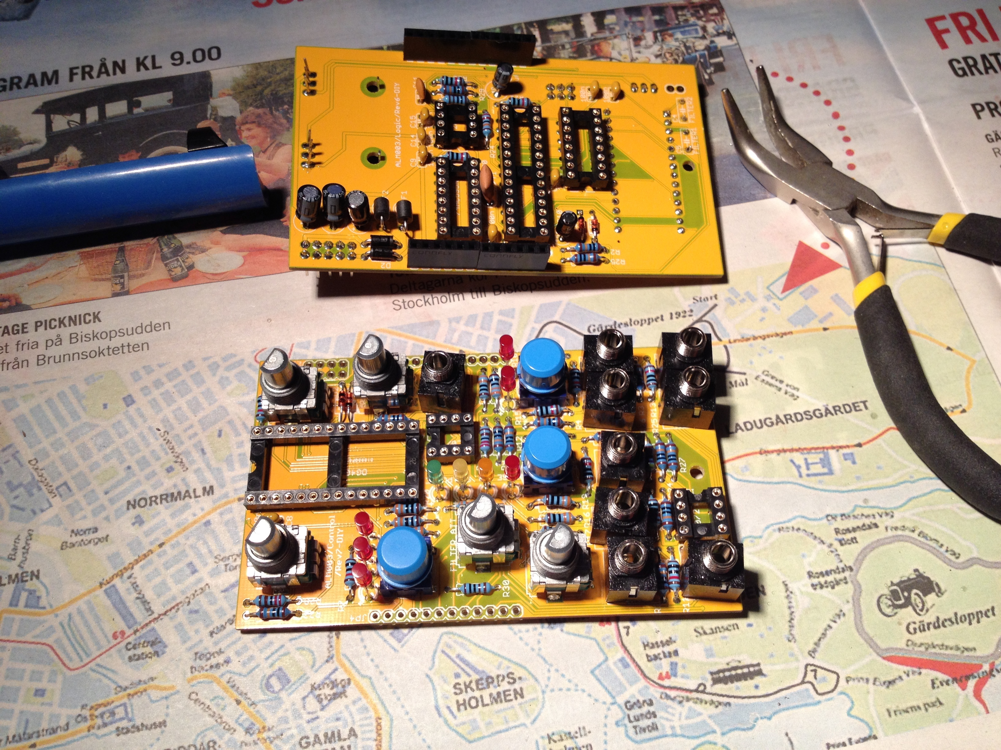
I really didn’t have room for the SID GUTS in my modular budget so I bought it as a kit because that allowed me pretend that it was a crafts project instead. ALM sells (or sold) complete kits with PCBs, the panel, all the knobs, buttons and other components, a very good build instruction and, optionally, a SwinSID. The software is open source and available for download so if you want to brew your own firmware that is possible too.

This is the SID GUTS kit prior to being massacred by an amateur.

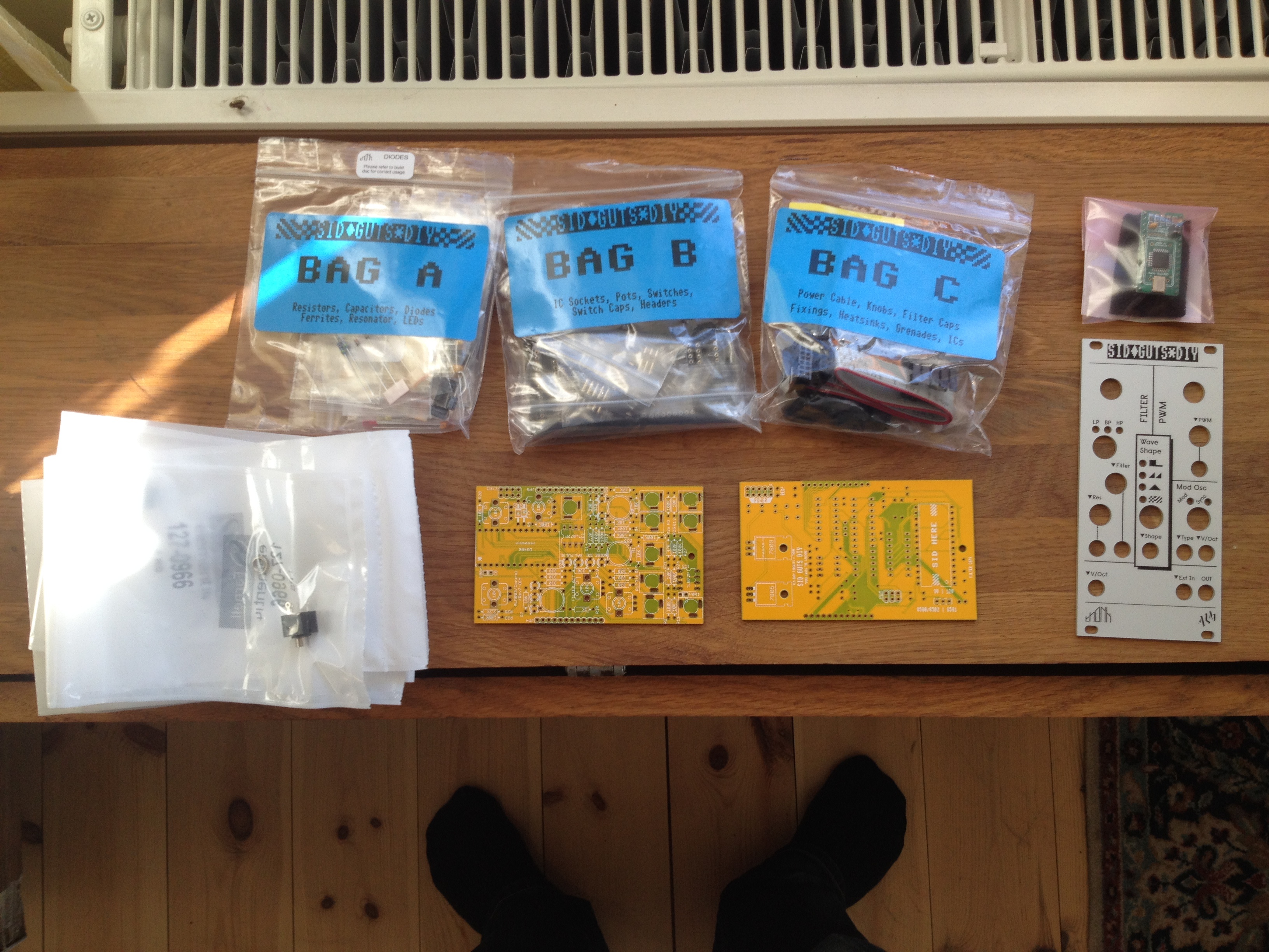
Building the kit was great fun. It pays to have some experience soldering because debugging a badly soldered pin can be seriously tricky. I’m by no means an experienced solderer and although I have dabbled, in hindsight I should have done a couple of practice runs to brush up before starting on the real build. Some of the solder joints, particularly the early ones, ended up a little anaemic but the only really bad one was a pin that I missed completely. Happily that was fairly easy to see once I gave the board a careful inspection.

SID PCB
This is where the SID goes. You did remember to get one, didn’t you?
The pots and jacks must be aligned with the panel before soldering them onto the PCB.

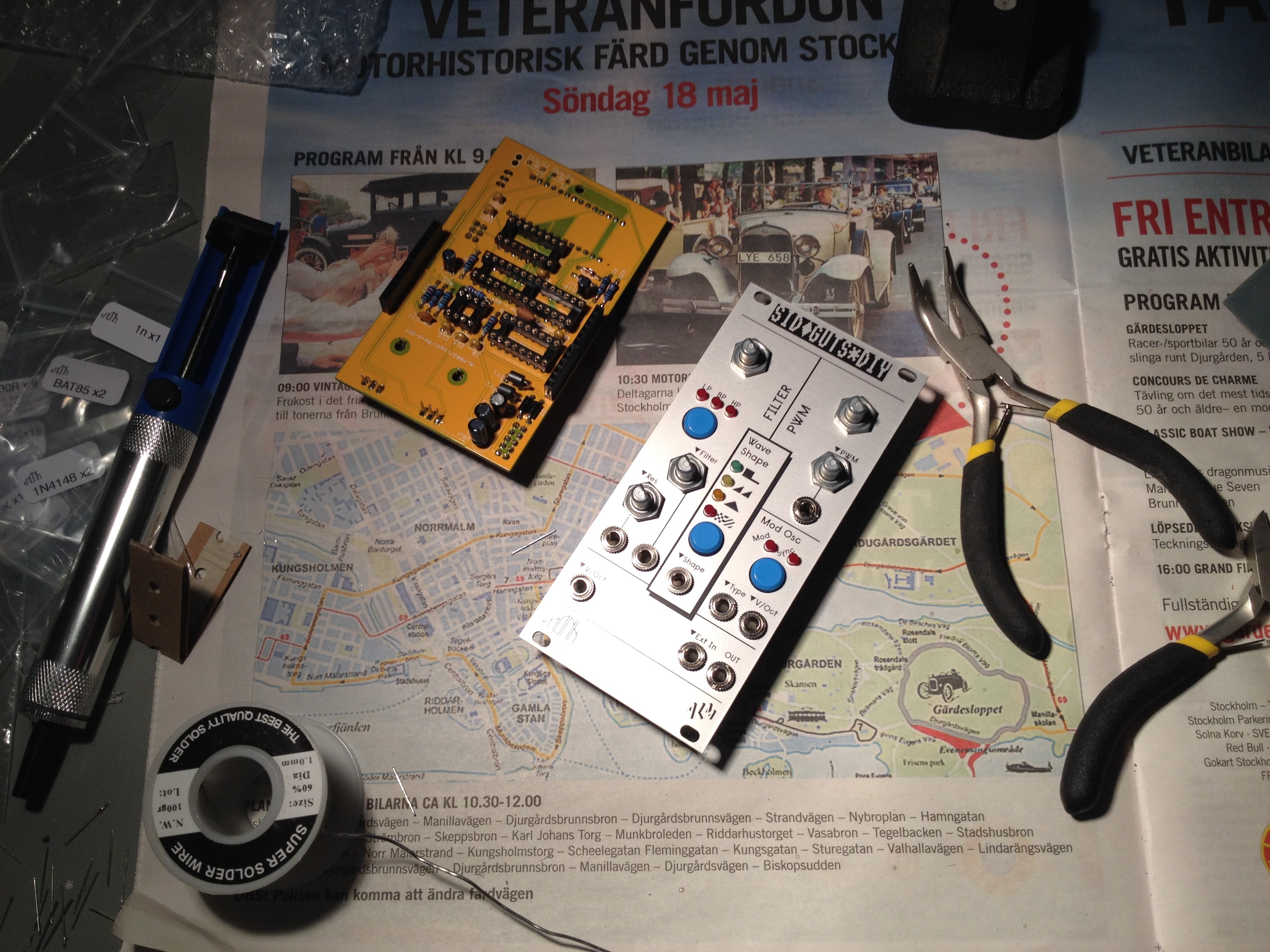
I did make one other mistake. The SID GUTS consists of two boards that are joined together, sandwich style, using four single-row pin-headers. Following the instructions, I soldered the male and female parts of the pin-headers onto their respective boards separately. However, I ended up soldering the female parts at a slight angle. This made joining the two boards a difficult and nerve-wracking experience — I had to use so much force bending the pin-headers to get the pins to fit that I was afraid I’d break the boards in half. Naturally the previously mentioned unsoldered pin was at this point A) undiscovered and B) unreachable so I had to separate the boards and rejoin them an extra time to fix that. In hindsight I should have joined the male and female parts of the pin headers together first, then put the boards together, and then soldered the pins to the board. Lesson learned.

Almost done. Mating the two PCBs should be no trouble at all really...
Almost done. Mating the two PCBs should be no trouble at all really…

Conclusion

So what do I think of the SID GUTS? It was fun to build. It looks cool and it certainly sounds retro. Is is useful? For sound effects, definitely. I don’t find myself using it much for melodies due to tuning issues but I would not definitely blame that on the SID GUTS — it could just as well be down to pilot incompetence. When it comes down to it, can you really resist having a SID in your modular? If you can then you’re probably from a different generation than me.

A Bug’s Life : The One Sample Solution

At one point in my life I found myself working for a company that made synthesisers of the musical instrument kind. The guts of the synths consisted of a bunch of DSPs that did all the audio processing, some memory, and a general purpose CPU that handled the rest: scanning the keyboard, scanning the knobs and buttons on the control panel and providing MIDI and USB connectivity.

One of my jobs was to clean out a list of bugs that users had reported on a released product. Most of these bugs were minor and sometimes obscure but the company prided itself on high quality so they would strive to fix all reported bugs, no matter how minor. Unless the bug report was that “the product should cost 50% less, be all-analogue, and be able to transport me to my place of work”. Some people have strong feelings of entitlement.

One of the bugs on my list was that the delay glitched if you turned it off and on again quickly. A delay is a type of audio effect that simulates an echo: if you send a sound into it then the sound will be repeated some number of times while fading out. Early delays were implemented using magnetic tape. If the recording head was placed some distance ahead of the playback head then a sound that was recorded into the delay unit would play back as an echo a short while later as the tape passed by the playback head. In this particular case the delay was digital and consisted of a circular buffer of audio samples that the DSP would continuously feed data into (mixed together with feedback from audio that was already in the buffer). The buffer would then be played back by being mixed with the main audio output signal.

A tape-based delay effect unit.

The delay had an on/off button on the front panel of the synth and when you switched it off the DSP would set the input volume to the delay buffer to 0 so that it would fill up with silent samples. However, since this happened at the normal audio rate it would take a few seconds before the whole buffer was filled with zeros. A user had discovered that if you played something with the delay enabled, then switched it off and then quickly switched it on again then parts of the delay buffer would still contain sound that you would hear, sometimes with nasty transients. The solution was to program the DSP to quickly zero the delay buffer using a DMA transfer whenever the delay was turned off.

This may sound trivial but the code running on the DSP was hand-coded assembly optimised to within an inch of its life. The DSP had one job: to present a pair of completely processed 24-bit samples — a stereo signal — to the Digital-Analogue converter inputs at the sample rate, which was 44100 times per second. If a sample wasn’t ready in time then digital noise would result at the output. This was frowned upon because it would sound horrible and if it happened while the instrument was being played on stage, through a serious sound system, you might as well poke out the eardrums of your audience using an ice pick. This made the rules of the game for the DSP pretty simple: if it could execute one instruction per cycle and was running at F cycles per second then that meant that it could spend N=F/(2*44100) instructions per sample. In fact it had to spend exactly N instructions or the timing would drift off. Any unused cycles had to be filled in with “No-op” instructions that do nothing but waste time. In this case N was a couple of hundred cycles. This meant that the DSP code was a couple of hundred instructions long, which was good because there was not so much of it, but bad because there were very few unused cycles left in which to set up the DMA.

This type of DSP is built to do one thing: to perform arithmetic on 24-bit fixed point numbers. It is a multiply-add engine. Multiplying and offsetting 24-bit fixed point numbers is easy and everything else is a pain in the upholstery. Instructions are often very limited as to which registers they can operate on and the data you want to operate on is therefore, as per Murphy’s law, always in the wrong type of register.

After scrounging up some spare cycles I managed to set up a DMA that zeroed the delay buffer whenever it was turned off. Apparently. I tested it: no problem. I told my boss and he came in and listened. Now, my boss had worked with theses synths for years and years and he immediately heard what I didn’t: a diminutive “click” sound that was so weak that I couldn’t hear it at all. “Probably you didn’t turn off the input to the delay buffer so a couple of samples gets in there while the DMA is running.” I verified it but no, the input was properly turned off.

Everyone needs Wilson's Common Sense Ear Drums.
Everyone needs Wilson’s Common Sense Ear Drums.

Now that I knew what to listen for I could hear the click if I put on headphones and turned the volume up. Headphones are always scary when programming audio applications because if you screwed up the code somewhere you might very well suddenly get random data at the DACs which means very loud digital noise in the headphones which means broken eardrums and soiled pants in the programmer. In contrast, a single sample of random data at 44.1kHz sounds a little bit like a hair being displaced close to your ear. In the beginning I had to stop breathing and sit absolutely still to hear the click noise. Moving the head just a little would make mechanical noise as the headphones resettled, noise that would drown out the click. After a while though, my brain became better at picking out the clicks, after a day or so I could hear it through loudspeakers. Unfortunately I soon started to hear single-sample clicks everywhere…

"Wait, wait! I think I can hear it!"
“Wait, wait! I think I can hear it!”
The good thing about this bug was that it was fairly repeatable. I like to think that no repeatable bug is fundamentally hard. Unless the system is very opaque you just have to keep digging and eventually you’ll get there. It may take a long time, but you’ll get there.

So what was going on? Was the delay buffer size off by one? No. Was the playback pointer getting clobbered? No. Did the DMA do anything at all? Yes, by filling the buffer with a non-zero value and then running the DMA I could see that the buffer was zeroed afterwards. Was it some sort of timing glitch that caused a bad value to appear at the DACs? Not that I could tell. Blaming the compiler is always an option but in this case the code was hand-written assembly so that alternative turned out to be less satisfying. A compiler can’t defend itself but your co-worker can…

brainstorm-blame-workplace-ecard-someecards

The debugging environment was pretty basic. The only tool available was a home-grown debugger that could display something like 8 words of memory together with the register contents and not much else. Looking through a megabyte or so of delay buffer data through an 8 word window might sound like fun but I guess I’m easily bored…

One thing that became apparent after a while was that the click sound would appear even when the delay buffer was empty to begin with. This indicated that the bad data was put there instead of being left behind. At this point I started to throw things out of the code. I find this to be a pretty good way forward if a bug checks your early advances. Remove stuff until the bug goes away, then you can start to add stuff back again. After a while I had just the delay code left. I wrote a routine that filled the delay buffer with a known value, ran the DMA, and then stepped through the whole buffer, verifying the contents word-by-word. And bingo, it found a bad sample.

bingo2

Seeing it made it real. As long as I only heard it, the defect could theoretically have been introduced somewhere later in the processing or in the output chain. But now I could see the offending sample through my tiny window, sitting there in the middle of a sea of zeros. What is more, the bad sample did not contain the known value that the delay buffer was initialised with. At this point suspicions were raised against the DMA itself. A quick look through the DSP manual revealed an errata list on the DMA block several pages long. This DSP had a horrendously complex DMA engine that could do all sorts of things. For example, it could copy a buffer to a destination using only odd or even destination addresses — in other words it could copy a flat buffer into to a single channel of a stereo pair. It seemed like half of these modes didn’t really work.

None of the issues listed in the errata list fit what I was seeing but I still eyed the DMA engine suspiciously. I therefore tried to zero the delay buffer using a different DMA mode and it worked! Ah, hardware: can’t love it, can’t kill it. Hardware designers on the other hand…

bad_dog

So the bug was put to rest and I moved on to the next issue on my list. Did we learn something? When you can’t blame the compiler, blaming hardware remains an option. In the end I came away pretty impressed by the dedication to quality and stability that this small company displayed. The original bug report was on a glitch that many companies wouldn’t bother to correct at all. The initial fix took maybe half a day to implement and took the amount of unwanted data in the delay from 1-2 seconds (between 90000 and 180000 samples) down to just a single, barely audible, sample in what was already a rare corner case. Fixing it completely took about a week. In other words, it took four hours to fix 99.99999% of the bug and 36 hours to fix the rest of it. But the message was pretty clear : fix it and fix it right.

And to all the semiconductor companies out there: don’t let your intern design the DMA engine.

Eurorack?

Eurorack is a type of modular synthesiser. In a non-modular synthesiser the various functional blocks that generate and modify sound (such as oscillators and filters) are preconfigured — they are connected in a predetermined way. In a modular synth these blocks are connected manually using patch cables. This makes them harder to use but more flexible. It also makes them expandable; if you need another oscillator you just buy another oscillator module. There are several different modular synth formats. Eurorack is popular because it is open, the modules are physically small and there are many hundreds of modules to choose from, from a large number of manufacturers.

A fixed architecture synth. The oscillators, filters and envelopes are pre-connected.
A fixed architecture synth. The oscillators, filters, amplifiers and envelopes are pre-connected.


A modular synth. The oscillators, filters, envelopes, amplifiers and other gadgets are manually connected with patch chords. Each sound can have it's own synth architecture.
A modular synth. The oscillators, filters, envelopes, amplifiers and other gadgets are manually connected with patch chords. Each sound can have its own synth architecture.


Modular synth fans have a tendency to go slightly overboard.
Another modular synth. Modular synth fans have a tendency to go slightly overboard.


A Self-centered Introduction

My anorak.
My anorak.

In this blog I’ll talk a little bit about my journey into Eurorack-hood. What modules I’m looking at, what I want to do with the system and perhaps some reviews of the components once I get a working system installed. Hopefully it can function as a kind of beginners guide to Eurorack modular synths. But why would a person choose to expose himself to a sordid world of holy wars, rabid gangs and addiction? Is it even a choice, or is it an inevitability caused by the social structures of my upbringing? The answer must surely be found in a brief narcissistic soliloquy…

My youth was profitably wasted playing computer games, reading about computer games and collecting huge stashes of pirated computer games (on cassette tapes, no less). At about the same time I graduated from my trusty C64 to an Atari ST I started to get interested in synthesisers. The ST was the musicians computer of that age because it had built-in MIDI. The Atari magazines would sometimes include reviews of sequencer softwares like Cubase and sometimes even actual hardware synths. I listened to a lot of Front 242 and played with an interesting tracker-type program called Quartet and dreamt of having a synth that could make cool sounds. Then I bought a Roland D5. I kept dreaming of having a synth that could make cool sounds.

roland-d5
The slightly less than classic Roland D5.

Well, perhaps that’s a bit unfair. The Roland D5 wasn’t that bad. The keys were good and the “LA-synthesis” was a kind of poor-mans sample playback that made some decent impressions of real-life instruments. But the D5 had no effects (I should have gotten a D10), no sequencer (I should have gotten a D20) and was easier to program than a Yamaha DX7 (I should not have gotten a DX7). It was programmed by stepping cryptic 8-bit values using a plus and minus key while peering confusedly at the lavish 16 by 2 character display and wondering wether “TVF Freq KF” would be better at 1/2 or 5/8 and why. On the plus side it did have a Cowbell patch.

cowbell
You always need more cowbell.

Basically, I couldn’t make the D5 sound cool and Front 242 had an Emulator II and there was no way in hell I could ever afford that so I went back to computer games.

After a while though, I read about the Nord Lead virtual analog synth and thought that that seemed like a much better way of learning synthesis. It had knobs for everything. It was Swedish. It was red. Jean-Michel Jarre had 5 of them. I drooled for months and then splurged on a slightly used Nord Lead 2 and (wiser this time) a Zoom 1204 multi-effect unit.

jarre
Jean-Michel Jarre receives the very first Nord Lead 2.

This turned out to be a lot more fun. I could actually learn the basics of subtractive synthesis on the Nord Lead 2 and I could even put some reverb on it. Ok, I drenched everything in reverb. I’m a real sucker for reverb.

I could totally not play though. I never really got the hang of the sequencer programs: I played so poorly that they never could quantize my creations properly and when I tried to program using the grid they would never keep an accurate beat.

On the theory that more gear would cure my inability to play I bought a Yamaha A4000 rack-mounted sampler which had both knobs and a pretty cool Grand Piano sample if you could stand waiting for it to load. I really wanted to use the A4000 more than I did but every time inspiration struck it would be 30 minutes of swearing over Windows sound drivers, 10 minutes of staring at the A4000 display, 10 minutes of playing around with the sound and 240 minutes of Baldur’s Gate.

The Yammy A4000 in a restful pose.

Then came Reason. I loved Reason because I didn’t have to muck about with all that other stuff. It just worked. I would play around with the Subtractor and it was a bit like the Nord Lead (which isn’t all that surprising if you know the history). I took the leap and switched from Windows to Mac, which is perhaps less dramatic for a Unix-nut (they both suck, but at least the Mac sucks less). But it was when I got Reason 6.5 that the penny dropped. Thor. Thor was complicated and scary and could say “I Am Thor” like a deaf person. It turned out that a guy named Gordon Reid had written a series of Thor tutorials that were published on the Propellerhead web site and once I started going through those the truth emerged : Thor is awesome. One thing in particular makes it awesome (for me) and that is the modulation matrix. Having a bunch of switchable oscillators and filters is all well and good but it’s when you want to control the LFO rate with an envelope, and you can, that the excrement gets tangible.

So now I’m a happy Reason-user. My Nord Lead 2 and A4000 gathers dust, the D5 was donated to the needy. I’ve even managed to put together some “music” that I will only inflict on my closest friends and most hated enemies. So why the heck do I want to ruin my life with a modular synth?

First and, let’s be honest, foremost, modular synths are cool. Like a bowtie or a Fez. Who wouldn’t want a wall full of knobs, patch cords and blinking lights, and where can those people get help?

A modular synth is _this_ cool.
Modular synths are this cool.

Secondly: I’m renovating an old room so that I can finally have the space I need to keep all my gear connected and organised. It has to have a 19-inch rack for my rack-mounted gear. Tallying up the height requirements of my vast equipment stash I came up with 3U. 2U for the A4000 and 1U for the 1204 effect unit. I will never use them again and they have to be rack mounted so they won’t figure that out. But a rack with 3U used is just pathetic, I need more rack-mounted gear!

Thirdly: While I have a fair grasp of the basics of subtractive synthesis and have a non-strict “no presets” policy for my music, there is lots more to learn. If I need a flute-sound or an analogue bass drum I can dial that up from scratch but once you need the more advanced stuff like ring-modulation, oscillator sync or (god forbid) FM, I can play with it, but I can’t use it with a goal in mind. Now it turns out that Gordon Reid (remember him?), that titan among men, has written a hugely ambitious series of articles about synth programming called “Synth Secrets“. Synth Secrets ran in 63 (!) installments in the great magazine “Sound On Sound” and is available online. It is also the final motivation for my modular future : I’m going to build a Eurorack system (because it is cool) and use it to build the patches in all 63 articles of Synth Secrets. After that I’ll come out the other end poorer, older and slightly harder of hearing. Or, if my 45 minute epic “856Hz Sinewave and Timpani” becomes the hit it will deserve to be, a millionaire. I’m not saying I will blog about all 63 lessons, or necessarily any of them. I will primarily write about designing and installing the actual system and, perhaps, review some of the modules once they are making noise properly.

So the goal here is not to build a 1000-module behemoth (at least not yet), but a pretty basic system. I’m going to control it from Reason, so no sequencers, and I won’t be digging into any of the esoteric math modules or any of the other crazy stuff.

Exclaimer!

Beware, for I am not an electrical engineer. While I have some hazy mental model of voltages and currents, and have managed to solder simple components without setting myself on fire, I really have no clue what I’m talking about. So please, for your own safety, judge all information on these pages as if I’m actively trying to kill you. Another way of looking at it is to read every sentence as if it ended with “, apparently.” Corrections are most welcome!

You should perhaps also know that I’m far from an audiophile or an analogue nut. I don’t think the terms “analogue” or “digital” really tells you anything about the sound and I don’t expect my modular system to sound better than Thor or the Subtractor in Reason. It might, and I’ll be interested to hear what my ears think, but I don’t expect it to. The attraction of the modular for me is the immediacy of knobs and the flexibility of patch cords.

In closing: Welcome and lets geek out!

Some Holistic Considerations

When it comes to designing a system I found it very helpful to use a “modular planner” website. There are a couple of different ones out there but I’ve found www.modulargrid.net to be the best by far. It has a huge database of modules that you can drag onto a rack so you can try out different layouts. It tallies the current draw and cost of your picks so it gives you helpful ballpark figures for these important metrics. As an added bonus it allows you to show off your creation to others.

The Eurorack format specification was defined by Doepfer and it can be found on their web page:
Technical Details :
http://www.doepfer.de/a100_man/a100t_e.htm
Mechanical Details :
http://www.doepfer.de/a100_man/a100m_e.htm

We’ve established that I’m building a fairly traditional subtractive analogue synth: an East Coast style modular. Modular synthesizers were pioneered in the 1960s by Bob Moog on the American east coast and Don Buchla on the American west coast.
Actually it seems that most countries had at least one crazy bearded guy who built a modular synth before everyone else in the world, but no-one cares about those guys. Anyway, an East Coast (Moog) instrument is usually played by means of a keyboard captained by a serious man in a suit.

All inhibitions are lost at a lively east coast performance.

A West Coast (Buchla) instrument is usually played by injecting psychedelic drugs in the audience and waving various extremities in the general vicinity of the synth.

A west coast player jams on the Buchla Breath Controller.

As a further illustration of the difference I will now list the modules that I planned to get at one point for my system, as well as the modules for a possible West Coast type system that I picked out on modulargrid.net

East Coast :
Doepfer A-190-2 MIDI/CV Interface
Doepfer A-110 VCO
Doepfer A-118 Noise Generator
Doepfer A-182-1 Switched Multiple
Doepfer A-140 ADSR
Doepfer A-132-3 Dual DVCA
Doepfer A-138 Mixer
Doepfer A-114 Ring Modulator
Doepfer A-148 Dual Sample&Hold
TipTop Audio Z3000 Oscillator
TipTop Audio Z4000 ADSR

An East Coast type modular.

West Coast :
Harvestman Piston Honda
4ms Euro Noise Swash
Make Noise Maths
Make Noise dual Prismatic Oscillator
Make Noise Pressure Points
Malekko Heavy Industry Assmaster
WMD Micro Hadron Collider
Harvestman Zorlon Cannon
Synthetic Sound Labs Modulation Orgy
Bananalogue Serge 3P

A West Coast modular.

See what I mean? Did I just pick the modules with the weirdest looks and strangest names on modulargrid.net? Maybe I did. But I’m not that far off. And now I’ve managed to make a system I haven’t even bought yet seem a little boring…

Ok, ok. The main difference between the two styles lies in how sound is generated and shaped. The East coast style is to generate sounds using simple waveforms and shape them using filters and envelopes. The West coast style is to use advanced modulation techniques to generate harmonically complex sounds directly. And then drugs.

Anyway, I looked around for “starter” systems a bit but found surprisingly little. TipTop Audio has a “Happy Ending” kit which seems to be just an enclosure with a power-supply. Pittsburgh Modular has the “Foundation” system which looks nice and Doepfer has a “MiniSystem” which looks similar to the Foundation but is quite a bit cheaper. I chose to go with Doepfer as my “default” — if there is a Doepfer module that solves my problem, I’ll go with that unless I have a compelling reason not to.

Why Doepfer? They pioneered the Eurorack format. They are “competitively priced” (because “cheap” sounds cheap). They’ve been around for ages and have loads of modules. When I emailed them to ask if their 6U-enclosure could be split into two 3U halves I got a reply from Doctor Dieter Doepfer himself (it was “no,” in case you were wondering (but more politely put)). And yes, yes, I know that Americans did it first, but let’s face facts : a modular analogue synthesiser is a very German instrument.

An italian masquerading as a german weakens my point.

The Enclosure

The Doepfer MiniSystem looked cool but I want to rack-mount my system so the cheap wooden box (the A-100LC6) it comes in would have to be replaced. I’ve basically settled on a A-100G6 which is a 6U (so it has two rows for modules) metal enclosure with rack-ears. It comes with a 1200mA power supply (which seems to be plenty) and a common bus for the two rows. It looks sturdy with decent room for expansion, should the fancy take me.

A lonely A-100G6 awaiting tennants.

So the way the Eurorack system works is that you have a “bus” which supplies power (+12V and -12V, +5V and ground), CV and Gate signals. Not all modules use all the signals. Many modules don’t need the +5V pin and the standard Doepfer power supply doesn’t even supply power to that pin without an extra adapter. None of the modules I’m considering needs 5V so I’ll do without the adapter. One (and only one!) module on the bus can use the internal CV and Gate signals as outputs. In my case it will be a MIDI-CV interface module. Other modules may use the internal CV and Gate signals as inputs and in this case several can do that at the same time. All other connections have to be made using patch cables in the front of the system.

Each module is connected to the bus using a ribbon cable and apparently these cables are often incorrectly built. If the cable is incorrect or connected the wrong way you may end up letting the blue smoke out of the module you’re connecting (that’s bad). I’ll be sure to inspect each cable carefully before using it.

MIDI-CV Interface

Doepfer has a couple of options here that boil down to combinations of these two questions:

A) Do you need a USB connection or is a regular MIDI connector enough?

and

B) Do you need MIDI Clock?

A built-in USB-MIDI interface is a little more flexible than the traditional DIN-type MIDI connectors since you won’t need an extra adapter when controlling the system from a computer. All interfaces have regular MIDI connectors (the 5-pin DIN type) so if you want to connect a keyboard or an old sequencer or something you should be set either way. In my case I already have a USB-MIDI dongle so I think I can save a few bucks by skipping the USB option.

MIDI Clock is a bit trickier. The primary use is to synchronise any sequencers you have in your modular system with external sources. MIDI Clock could be potentially useful even if you don’t have a sequencer module though. It seems nice to have a clock source available in the system, for example to synchronise an LFO with the song tempo. Unfortunately the price difference between a simple MIDI-CV (MIDI-CV/Gate) interface and one that can also handle MIDI Clock (a MIDI-CV/Gate/Sync) is pretty substantial.

I haven’t really decided yet. I imagine that my needs are pretty basic so my current pick is a Doepfer A-190-2 MIDI-CV/Gate interface. It is a cheap, no-frills interface. However, Doepfer has the A-190-4 MIDI-CV/Gate/Sync interface coming out this spring and I may end up feeling that I can’t live without MIDI Clock. It’s my first module and the Euro-quicksand is already pulling me in!

The Doepfer A-190-2
The Doepfer A-190-2

Oscillators

Oscillators are one of the two big ticket items (the other being filters). There is no limit to the amount of crazy you can find here. I’m trying to put some upper bound on the craziness of my initial system so my picks are pretty traditional (you’ll hear this again!).

My first pick is a Doepfer A-110 Standard VCO. It goes for about 140 Euros and is a pretty basic oscillator that outputs sine, triangle, sawtooth and square waves on separate outputs. The output frequency goes from 15Hz to 8kHz which goes as “basic” I guess — not great. The A-110 has two CV inputs controlling the pitch so you can do basic frequency modulation. The pulse width of the square wave if also CV-controllable. Finally, the A-110 has a Sync input which can be used to hard-sync it to another oscillator. The A-110 oscillator may need up to 20 minutes of warming up before the tuning becomes stable — welcome to analogue land!

The Doepfer A-110 Oscillator.

So the A-110 is basic and has what I need. However, a modular synth with a single oscillator is pretty boring, you’ll need at least two to get things interesting. Initially I planned on getting two A-110s. There are things to be said in favour of having two oscillators of the same type: they are more likely to track similarly across the octaves and detuning them to make a sound fatter is probably more likely to have the intended effect.

I had basically settled for two A-110s when I started to look at which LFO I wanted. The thing about the LFO is that the frequency has to be voltage controllable. One of my favourite effects is sweeping the LFO rate with an envelope (imagine creaking ice or the sound of a mooring cable being strained) so I definitely want a CV-controllable LFO rate. The basic Doepfer LFOs (A-145, A-146) does not have this but the A-147 VCLFO does. When I was digging around looking for an LFO it struck me (well, it struck someone who wrote about it on a forum via which it then struck me) that if I got an oscillator that could go down into really low (like a tenth of a Hertz) frequencies I could use that as an LFO and when I’m not using it as an LFO I’d have a free oscillator!

Ok, so “free” turned out not to be what this extra oscillator was going to be. Since the A-110 doesn’t go below 15Hz it is not a viable LFO-replacement candidate. This is when I found the TipTop Audio Z3000 Smart VCO Mark II. On paper the Z3000 is a lot more powerful. It does everything the A-110 does — square, sine, saw and triangle waves on separate outs, hard sync, CV-controllable PWM — and it has some extra goodies to tempt you away from your liquidity. It has a frequency counter display which allows you to set the oscillator frequency exactly and it can be used to measure the frequency of external signals as well. The Z3000 frequency range is 0.7Hz to 30kHz. It has a waveshaping input, which does something, and a Hard Sync Modulation input, which does something else. It’s significantly more expensive than the A-110 at about 220 Euro but if I replace one A-110 and can save on buying a dedicated LFO then it’s a wash. Right? Right? What happened next was typical.

The TipTop Audio Z3000 Smart VCO mk2.

What happened was that I read the manual to the Z3000. Never read the manual. At first a particular module is something you want. If you then read the manual the module becomes something you need. It’s a “Yesterday I didn’t know that it existed and today I cannot live without it” kind of thing. I like the possibility of setting exact, matched frequencies when using a pair of oscillators as parallel sound sources. So the Z3000 looks like it would be particularly well matched by another Z3000. So maybe two Z3000 oscillators and no A-110s…

It would be nice to have one of each because I’m curious about how pronounced the difference is between different oscillators — the naive assumption would be that for instance a sawtooth wave would sound much the same on all oscillators. On the other hand I do have a budget and the beauty of the modular system is that I can get another oscillator later if I want to.

Finally, I need a noise source. Maybe not strictly speaking an oscillator but as a sound-generator I’ll deal with it under this heading as well. Noise is a lot more versatile than you would think but I don’t need anything fancy so I’m going with the Doepfer A-118 Noise/Random module. It has outputs for white noise, coloured noise (high or lowpass filtered noise) and random voltage. The random voltage output is a low-pass filtered version of the coloured noise so that you get a lower rate of change which is useful for CV (rather than audio).

The Doepfer A-118 Noise Module.

To summarise the sound-generating section:
2 TipTop Audio Z3000 MKII Oscillators
1 Doepfer A-118 Noise/Random

Input

I absolutely want to be able to use an external sound source with my system. I’d quite like to compare the Nord Lead oscillators using the Nord Lead internal filter to the same oscillators using the modular filters for example. Or to use Thor as an oscillator with MIDI-control of the modular envelopes. Part of the point is figuring out what stuff actually sounds like. And part of the point is building grotesque Frankenstein patches.

There are various “external input” modules available (like the Doepfer A-119) but as far as I can understand I won’t need one. The modular should be able to accept a line-level input from my mixer directly.

Low Frequency Oscillator

I may possibly have motivated the step up to the posher TipTop oscillators by claiming a savings from making do without a dedicated LFO. But that was many paragraphs ago and the sacrifice has served its purpose. Of course I need a dedicated LFO! I’ll go basic here as well since my oscillators do support LFO frequencies and I think I should be able to get an LFO out of Reason via the second CV output of the MIDI-CV interface. The Doepfer A-145 looks decent enough and costs a reasonable 65 Euros. It generates sine, square, triangle, sawtooth and inverted sawtooth waves and the cycle can be synchronised via a reset input. The frequency range goes from somewhere around 0.01Hz to 4-5kHz.

The Doepfer A-145 LFO.

I like using stepped random LFO waveforms for pads but those are not provided by the VCOs or LFOs I’m considering. Because of this I’m matching the A-118 Noise generator with an A-148. The A-148 is a Sample and Hold module; it has a sample input and a trigger input and will sample the level of the input whenever a trigger arrives and hold that level on the output until the next trigger arrives. Sample. And hold. Pretty simple. With this I can connect the noise source to the sample input and a square wave from an LFO to the trigger input and Chewbacca! : a stepped random waveform with the rate of change controlled by the LFO! It’s magic! Expensive, possibly pointless magic…

The Doepfer A-148 Sample & Hold.

LFO summary:
1 Doepfer A-145 LFO
1 Doepfer A-148 Dual S&H